When you want a shower, you want good pressure, and you want warm water - not too hot, and not too cold. There’s two ways to accomplish this: thermostatic valves and pressure balance valves. This post helps you understand the option, so you can decide which option is best in your new bathroom.
Here’s a quick summary:
The thermostatic valve is a fancier, more expensive device that automatically adjusts the temperature of the water internally without you needing to adjust the flow/pressure of the water.
A pressure balance valve is a lot cheaper, and it relies on your personal “skill” to increase or decrease the amount of hot water (or cold water) pressure, so you get the exact level of warmth you desire. In other words, if it’s too hot, you can either turn the cold valve higher, or you can turn the hot valve lower.
Alright, let’s dive in for some more detail…
Thermostatic Shower Valve: Keeping it Just Right
Let's start with the star of the show – the thermostatic shower valve. Picture this: you step into the shower, and with just a twist of the dial, you're greeted with a blissful cascade of water at your preferred temperature. Sounds dreamy, right? That's the magic of a thermostatic shower valve at work.
Benefits:
Consistent Temperature: One of the most significant advantages of a thermostatic valve is its ability to maintain a constant water temperature, regardless of fluctuations in water pressure or temperature elsewhere in the system. Say goodbye to those icy cold or scalding hot surprises mid-shower!
Safety First: Speaking of temperature control, thermostatic valves come equipped with built-in anti-scald features, making them a safe choice, especially for households with young children or elderly family members.
Luxurious Experience: With precise temperature control and the ability to preset your preferred temperature, a thermostatic valve elevates your shower experience to spa-like levels of indulgence. There are even digital versions that have an electronic interface and even wifi that enables you to control the water temp!
Disadvantage:
Cost: Let's address the elephant in the room – thermostatic valves tend to be pricier upfront compared to their pressure balance counterparts. However, considering the comfort and safety they provide, some may argue it's a worthwhile investment.
Pressure Balance Shower Valve: Simplicity with a Side of Safety
Now, let's turn our attention to the pressure balance shower valve – the reliable workhorse of bathroom fittings.
Benefit:
Cost-Effective: If budget is a primary concern, you'll appreciate the affordability of pressure balance valves. They offer a cost-effective solution for maintaining a comfortable shower experience without breaking the bank.
Disadvantages:
Temperature Fluctuations: While pressure balance valves do a decent job of stabilizing water temperature, they may not offer the same level of precision as thermostatic valves. You might experience minor fluctuations in temperature, especially when other water sources are in use simultaneously.
Limited Temperature Control: With pressure balance valves, you have control over water temperature to some extent, but don't expect the same level of precision as a thermostatic valve. If you're particular about your shower temperature, you might find this lack of fine-tuning frustrating.
Choosing the Right Valve for Your Project
In the battle of thermostatic vs. pressure balance shower valves, there's no one-size-fits-all answer. Your choice will ultimately depend on factors such as budget, installation requirements, and the level of temperature control and safety you prioritize.
For those seeking ultimate comfort, safety, and a touch of luxury, the thermostatic shower valve is the clear winner. However, if you're looking for a practical, budget-friendly option that still ensures a comfortable shower experience, you can't go wrong with a pressure balance valve.
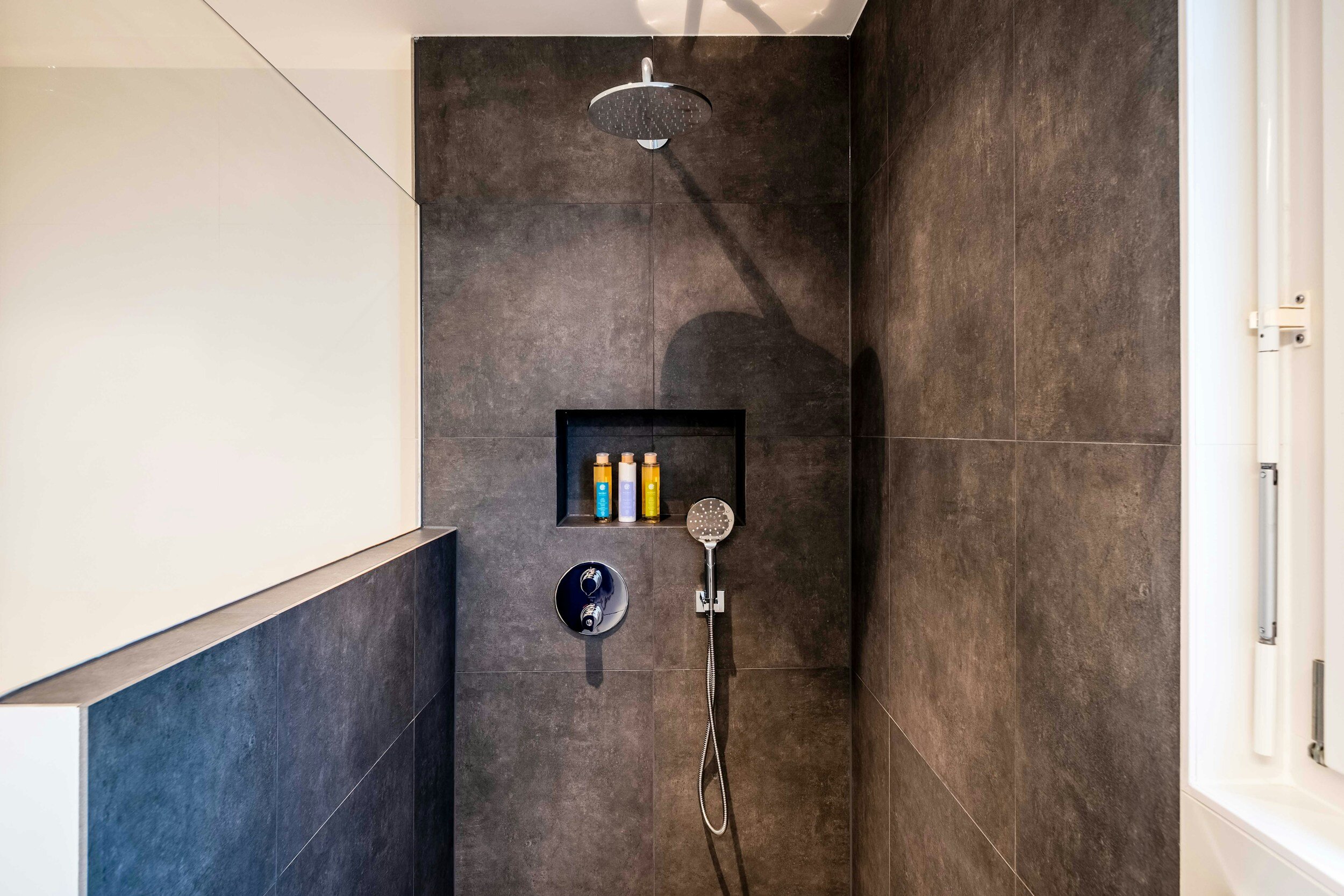
And there you have it – a friendly guide to navigating the world of shower valves. There’s also many more options available such as multiple shower heads, diverter valves to turn on certain shower heads and/or shower wands, and don’t forget about rain heads mounted into the ceiling and even multiple sprayers mounted in several different heights on the wall. You can even add a steam component to a shower! Feel free to ask for more detail. Happy showering!
If you’d like to learn more about our design process, visit www.josharch.com/process, and if you’d like to get us started on your project with a feasibility report, please visit www.josharch.com/help